Monday, January 24, 2011

Introduction

How does an engine works?
How does the engine start up in the first place?
How does the reciprocating motion of the piston converts to rotary motion of the propeller?
How does the piston gains its momentum from?
How? When? Where? What? Who?

Ever came across your mind before?
We'll provide you with the best, relevant answers as possible.

Firstly, if you want to know what is really going on inside the engine or
technically, the cylinder, click on the following image which will re-direct you
to an animation of a four-stroke engine cycle.
Note: Set the play speed to its minimal and just observe 1 cylinder will do!


What about 2-Stroke Engines?
    2-Stroke Engine cycle in comparison to 4-stroke Engine:

2-Stroke Engine
4-Stroke Engine
2 strokes to complete 1 working cycle
4 strokes to complete 1 working cycle
Air intake through scavenge ports
Air intake through suction valves
Low Speed Engines
High Speed Engines
Higher power
Lesser power
Expensive parts
Cheaper parts


Advantages of 2-stroke Engines in comparison to 4-stroke engines:

1.  No suction valves, hence simple construction.
2.  Have a high power-to-weight ratio (engine has twice as many combustions per second as a four stroke engine revolving at the same speed).
3.  Have the potential for about twice the power in the same size (twice as many power     strokes per revolution).
4.  Lighter, and cost less to manufacture.

Disadvantages of 2-Stroke Engines in comparison to 4-stroke engines:

1.  Shorter lifespan as compared to four-stroke engines (parts wears out faster due to the lack of a lubrication system).
2 . Require a mix of oil with the gas to lubricate the crankshaft, connecting rod and cylinder walls.
3.  Costly.
4.  Less fuel efficiency.
5.  Produce more pollution.

Test

Test

Test

Combustion Period


  Rapid Combustion Period:
·    Between injection and the start of ignition.
·    Initial droplets enters the cylinder are being heated up by the surrounding charge air and starts to vapourise and ignite.

    Rapid Combustion Period:
·    Fuel that was accumulated during the ignition delay period starts to burn rapidly due to the pre-mixed combustion.
·    This period will be accompanied by a sharp rise in cylinder pressure and fuel injection still continues during this period.

    Steady Burning Period:
·    Combustion has been achieved and the fuel entering the cylinder will burn as soon as they have penetrated, heated, mixed and vapourised.
·    Cylinder pressure rises to its maximum value just after TDC, near the middle of the steady combustion period, and decreases gradually before expansion stroke begins.

   After Burning Period:
·    Combustion continues until the remaining fuel is burnt despite the fact that the injection stops.

Pictures of Parts


Crankshaft                      Connecting rod         Crosshead & Guide
 Cylinder head (4-stroke)         Cylinder liner            Cylinder head (2-stroke)
 Governor                       Fuel Injector                     Gudgeon pin
Fuel pump             Inlet & exhaust valves                   Piston
 Piston rings                     Turbocharger

 Push Rod & Rocker Arm             Piston Skirt

Related Videos

For a better understanding of the topic, please view the following videos:


Sunday, January 23, 2011

Cooling Water System


·         Fresh water generator produces freshwater from seawater.
·         Fresh water is circulated around the engine via cooling water pump to remove heat from cylinder liners, cylinder heads and exhaust valves.
·         Temperature of cooling is controlled by a 3-way control valve and outlet temperature is maintained at around 78-82°C.
·         A heater is used to maintain the hot cooling water when engine is not running to prevent the engine from experiencing thermal stress or to allow the water temperature to rise to a specific level before starting.

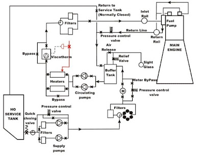
Fuel Oil System

 
5.3.1   Essential Components:
·         Fuel Pump
·         Fuel Injector
·         Fuel Delivery Pipe

5.3.2   Fuel pump:
·         Deliver a specific amount of fuel into cylinder through fuel delivery pipe and injector. The start and stop of fuel injection (with respect to crank angle), is determined at fuel pump.

5.3.3   Plunger controlled fuel pump Construction:
·         Consist of housing, a plunger & barrel, a plunger return spring, a geared control sleeve and a control rack.
·         The delivery valve assembly is mounted on top of housing. High pressure fuel discharged pipe is connected on delivery assembly.
·         Cam-operated plunger moves in a reciprocating motion within the barrel.
·         Plunger-spring pushes follower to maintain contact with cam.

5.3.4   Pumping principle:
·         Fuel enters pump through inlet connection and fills fuel chamber surrounding the barrel.
·         When plunger is at bottom of stroke, fuel flows through barrel ports (fills space above plunger, vertical slot cut in plunger and cut-away area below plunger helix)
·         As plunger goes up, barrel ports are covered and compression begins.
·         Fuel is discharged through lifted delivery valve into high pressure pipe.
·         Fuel delivery stops when spill port is uncovered.
·         Delivery valve returns to its seat and closes
·         Rest of fuel is spilled backed into fuel chamber.

5.3.5    Function of fuel injector:
·         Open and close the flow of fuel to combustion chamber
·         Convert high pressure oil from pump, into fine spray

5.3.6    Construction:
·         Consist of a valve body (which contains the spring and its compression nut). Mating surfaces between body and nozzle are ground and lapped to give a tight seal.

·         Upper chamber in nozzle is charged with fuel and sealed by needle valve when closed. Lower chamber is sealed by the seat of needle valve and has many atomizing hole (atomise and distribute fuel spray into combustion chamber).

·         A specific fuel pressure lifts the needle valve and oil flows to lower chamber. Additional area of needle mitre subjected to pressure and causes needle to lift rapidly (allow oil to pass through atomiser holes into combustion chamber at high pressures).

·         Valves will close under spring compression once fuel pump cuts off pressure.
 

Starting Air System


 5.2.1    Purpose of Air Start System:
·         A high pressured compressed air will start cranking the flywheel for a kick start on the crankshaft rotary motion process.
·         The energy produced from rotary motion of the crankshaft is then diverted to the reciprocating motion of the pistons.
 

 5.2.2   Operational System:
·         When starting the engine, compressed air enters into cylinder with the piston just over TDC pushing the piston downwards.
·         As the crankshaft starts rotation, the air start valve on the next cylinder in line opens to continue the momentum.
·         The starting air system is linked with the fuel system; hence fuel supply is restricted on starting to keep within a speed limit that has been set before operating at full speed.
·         Fuel is injected into the cylinders and the air is cut off when engine runs.  

Lubricating Oil System

5.1   Lubricating Oil System

    5.1.1   Purpose of Lubricating Oil:
1) Maintain oil film between piston rings and cylinder wall
2) Provide proper lubrication of camshaft valve gear
3) Provide oil film between shafts and bearing surfaces at main, crank pin wrist pin   thrust bearings and all other bearing.

    5.1.2    Types of Lubrication:
1) Splash
2) Pressure circulation
3) Forced feed

   5.1.3   Difference in Lubrication:
·         In 4-stroke engines, cylinder walls are lubricated by lub oil flowing into crankpin bearing through hole in connecting rod.
·         In 2-stroke engines, cylinder walls are lubricated separately by forcing lub oil between piston rings and liner (by cylinder lubricators). These lubricators are single-acting reciprocating high pressure pumps which pumps lub oil at each stroke, on the liner surface.


  5.1.4    Lubrication System:
·         Lub oil is stored in the sump (for 4-stroke) or drain tank (for 2-stroke).
·         The oil from drain tank is drawn by a lub oil pump through a suction strainer (prevents pump from being damage by foreign particles).
·         Discharged oil is passed on to a cooler where heat exchange takes place between lub oil and seawater (bring down temperature of oil to a suitable level for lubrication process).
·         Oil discharged from coolers flows into a manifold, which distributes oil to engine bearings/gearing (for lubrication), and to piston (oil cooled type).
·         After which, it runs into crankcase and a strainer before settling in the drain tank.
·         Centrifuge is used to purify lub oil system so that clean oil can be supplied.

5.1.5          Methods of Oil Treatment:

A.     Settling:
Oil from the engine is placed in a tank and is heated up.Foreign matter such as carbon, sludge and water will settle to bottom of tank, and leave only clean oil above (based on the principle that density of oil is lesser than water).  Hence, to separate clean oil, the contaminants can be drained out from the bottom.

B.       Centrifuging:
A "centrifuge" rotates the oil at high speed, creating a centrifugal force.
This lashes the heavy contaminants outward towards the circumference of the bowl where they are removed.

C.      Filtering:
Oil passes through materials (glass fibre, yarn, cotton, etc.) and foreign particles are absorbed.

5.1.6    Maintenance of LO System:
1) Pressure and temperature should be kept normal.
2) Oil must be purified regularly and changed when deteriorated.
3) Filters must be cleaned regularly.
4) LO must be analysed regularly and treated accordingly.
5) Engines and accessories should be maintained in good order (reduce contamination.

Operational Basic Systems

Click on the following schematic diagrams for more details on the respective systems.

 Starting Air System


 Fuel Oil System

  
 Cooling water system


Lubricating Oil System


Function of Parts

Parts in alphabetical order.

No.
Parts
Definition/Function
1
Connecting Rod
·         Changes the reciprocating motion of piston into rotary motion at crankshaft
·         Transmits the power produced at piston to crankshaft
2
Cylinder Block
·         Holds engine component (pistons, cylinders, camshaft and oil pump)
·         Hold crankshaft that converts rotating motion to reciprocating motion
3
Cylinder Head
(4-stroke)
·         Carries inlet and exhaust valve.
·         An injector is also mounted on cylinder head
4


Cylinder Liner
·         Forms a sliding surface for the piston rings while retaining the lubricant within
·         Receives combustion heat through the piston and piston rings and transmits the heat to the coolant.
·         Prevents the compressed gas and combustion gas from escaping
5
Crank Pin
·         Transfer  power and motion to the crank shaft which come from piston through connecting rod
6
Crank Shaft
·         Receives oscillating motion from connecting rod and gives a rotary motion to the main shaft.
·         Drives the camshaft which actuate the valves of the engine
7
Cam Shaft
·         Takes driving force from crankshaft through gear chain
·         Operates the inlet and exhaust valve with the help of cam followers,push rod and rocker arms
8
Crosshead
·         A beam that connects the piston rod to the connecting rod
9
Crosshead Guide
·         Allowing the crosshead to only move in the same direction as the piston travel
10
Fuel Injector
·         Delivers fuel in fine spray under pressure
11
Fuel Pump
·         Deliver metered amount of fuel into cylinder through fuel delivery pipe & fuel injector
12
Inlet Valve & Exhaust Valve
(4-stroke)
·         Inlet valve allow the fresh charge of air-fuel mixture to enter the cylinder bore
·         Exhaust valve permits the burnt gases to escape from the cylinder bore at proper timing
13
Gudgeon Pin
(4-Stroke)
·         Connects the piston with small end of connecting rod.
14
Governor
·         Controls the speed of engine at a different load by regulating fuel supply in diesel engine.
15
Piston Rings
·         Prevents the compressed charge of fuel-air mixture from leaking to the other side of the piston.
·         Oil rings used for removing lubricating oil from the cylinder after lubrication.
·         Prevents the excess oil to mix with charge.
16
Piston Skirt
·         Carries gudgeon pin and rub against liner.
17
Push rod & Rocker arm (4-stroke)
·         Push rods sit on the cam so when engine is running
·         Push rods go up and down in a timed sequence and with the rocker arms, open and close the inlet and exhaust valves.
18
Piston
·         Compresses air in between cylinder head and piston crown.
19
Scavenge Ports
(2-stroke)
·         Pushes exhausted gas-charge out of the cylinder
·         Draw in a fresh draught of air ready for the next cycle.
20
Stuffing Box
·         A type of seal that prevents fluids from leaking inside of machine parts.
21
Turbocharger
·         A device that uses the energy of exhaust gases coming out from an engine to compress the air going into the engine.